


Fridge or Freezer Compressor Not Starting? Test Start Relay, Overload, Capacitor, PTC Thermistor
- Craig Migliacco
- Apr 18, 2022
- 9 min read
Updated: Feb 26
This article explains how to troubleshoot a refrigerator or freezer compressor that does not start. There are different components that can be tested to find out what the problem is.

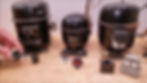
To begin troubleshooting, turn the power off to the compressor. If there is a plastic faceplate over the compressor tabs, remove this. There may be multiple different components inside that are mounted onto the 3 compressor tabs. Below are different examples of what may be found inside. Later in this article, we will cover the troubleshooting of each component.
Some compressors have terminals where there is one terminal above the other two. There are other compressors that have two terminals above the one terminal. Make sure to turn the power off and take a photo before removing any components. Each compressor is built differently as well as having different components.

Examining the Possible Components
External Compressor Protector: This is a protection device and there are two types. One is mounted directly on the common tab. The other version is round and is mounted on the shell of the compressor with a wire extending over from the common tab to the component. This device opens the electrical circuit to the common tab if there is high heat and/or high current drawn for an extended period of time. This device opens the electrical circuit to the compressor in case the compressor has a hard time starting. This is done so that the compressor windings do not melt.

Pill-Type PTC Thermistor: This is mounted to both the run and start tabs. This pill breaks the electrical circuit to the start tab after the compressor gets up to speed. Th component requires a few minutes to cool before it can be used for the compressor to start again.
Current Starting Relay (downward position type): This is mounted to both the run and start tabs. This breaks the electrical circuit to the start tab after the compressor gets up to speed. This resets immediately after use.

Current Starting Relay (vertical position type): This is mounted to both the run and start tabs. This is a different orientation than the previous one mentioned above. This breaks the electrical circuit to the start tab after the compressor gets up to speed. This resets immediately after use.
Start Capacitor: This is connected from the run tab to the start tab of the current starting relay. The start capacitor helps the compressor start by allowing a 90 degree phase shift in the electrical power feeding the start tab.

Time Starting Device: This is mounted to all three tabs. On the inside of the time starting device there will be an external compressor protector. On the back of the device will be a start capacitor.


Troubleshooting
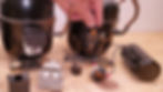
External Compressor Protectors: Turn the power off to the compressor. Remove the plastic or metal cover plate. Take a picture. Make sure the component has had a chance to cool down. Disconnect the component. Test the electrical resistance with a multimeter across the contacts.
Place one probe on the common wire or female connector and the other probe on the available terminal. The measurement should be between .1 to .3 ohms. If the resistance measurement is higher than this, there may be burnt contacts inside the component and the component must be replaced. If the component measures OL and it is cool to the touch and it has been at least 10 minutes since the compressor was last running, the component must be replaced.
The component is meant to open up the electrical circuit if there is high heat and/or high current at the compressor. There is a small section of electric strip heating wire within the component. There is also a thermo-disc on the inside. If drawing high amperage, the electric resistance coil will heat up in order for the thermo-disc to pop out of shape. When this pops, it opens up the electrical connection. However, it is supposed to close again after power is disconnected and the component has cooled down.

Be sure to allow time to cool before testing. Also, when replacing any of the components, it is important to replace them with the same specs. There is a model number stamped on the side. Be sure to replace with the correct model number.

PTC Thermistor: Turn the power off to the compressor. Remove the plastic or metal cover plate. Take a picture. Make sure the component has had a chance to cool down. Disconnect the component.
If either of the two following things are present upon inspection, replace the component:
- Inspect for burn marks.
- Shake it and if it makes a rattling sound, the pill thermistor inside is broken.
Measure electrical resistance across the two contacts with a multimeter. If the PTC thermistor is in good condition and it is cool, the resistance reading will usually be in the range of 3 to 6 Ohms. If the thermistor is not cool, the electrical resistance may be higher but it will fall as it cools. If you measure OL then the thermistor is likely broken and the component must be replaced.
If broken on the inside, the thermistor will not provide electrical power to the start winding and the compressor won't turn on. In this case, the external compressor protector will open up the electrical circuit to cut off power to the compressor before the compressor overheats.

Time Starting Device (TSD): Turn the power off to the compressor. Remove the plastic or metal cover plate. Take a picture. Make sure the component has had a chance to cool down. Disconnect the component.

The external compressor protector is integrated on the component and there is a start capacitor on the back. The start capacitor can be removed and tested by itself. On the back of the capacitor it may read 15 uF or another value.
Testing is done using the multimeter's capacitance reading. Set the meter to MFD or uF which both stand for micro-farads. Next, take a 10,000 Ohm resistor and rub across the start capacitor terminals to remove the residual voltage. Once this is done, place one multimeter probe on each of the two terminals. It can take about 5-10 seconds to get a good reading. If the microfarad measurement is within 5% of the rating on the capacitor, the capacitor is good. For example, the reading of 15.41 MFD for a 15 MFD rated capacitor is acceptable. If there is no value read, the value is over 5%, or there is visual damage, or leaking fluid on the capacitor, replace it with a new one.
The resistance value can be tested on the compressor protector. Set the multimeter to resistance. Place one probe into the compressor protector female terminal and one on the side terminal. The reading is normally .1 to .3 Ohms if the compressor protector is in good working order and is cool.
After checking the start capacitor and the compressor protector to verify that both are good, the only component left is the Time Starting Device which is a solid state device. There is no other testing method for this component. If power is applied to this component and the compressor protector and start cap are good and the compressor will not turn on, the Time Starting Device is likely bad and should be replaced. It is important to test everything around this component, since it is hard to test with its control board inside.
Compressor Testing: Also take note, the compressor could be mechanically stuck if high amperage is being drawn. Make sure to check out our other articles on testing compressors before condemning.
Current Starting Relay: There are different types of current starting relays. They can be presented in a downward or upward facing position. Some can have an integrated compressor protector mounted on the bottom. Others have the compressor protector externally mounted. After the electrical power is delivered through the component and to the compressor, the high current pulls the iron core upward and allows the run and the start to connect. Electrical current is sent to the start winding and will help the compressor start. The compressor begins to run and current lowers, resulting in the iron core falling down. The fallen iron core disconnects the start tap from the electrical circuit and the compressor continues to run. The compressor runs by the continued supply of electrical power between the run and the common terminals through the compressor protector.

Some current starting relays are integrated with a start capacitor and some are not, depending on the compressor. For those with a start capacitor connected, instead of the current starting relay connecting the run and start tabs, it allows the start capacitor to be connected. This occurs until the current starting relay opens the electrical circuit after the compressor is up to speed.
For those with a start capacitor, make sure to test the capacitor to see if it is good. Testing is done using the multimeter's capacitance reading. Set the meter to MFD or uF which both stand for micro-farad. Next, take a 10,000 Ohm resistor and rub across the start capacitor to remove the residual voltage. Once this is done, place one multimeter probe on each of the two terminals. It can take about 5-10 seconds to get a good reading. If the microfarad measurement is within 5% of the rating on the capacitor, the capacitor is good. For example, the capacitor may be rated between 88 to 110 MFD. If 92MFD is measured, the capacitor is good. If the meter reads OL, the capacitor is bad. If the meter reads 56MFD, the capacitor is bad. If there is no value read, the value is over 5%, or there is visual damage, or leaking fluid on the capacitor, replace it with a new one.
Troubleshoot the current starting relay: If the current starting relay is in the normally downwards position and the iron core is down, there should be no resistance value on this angle. Once it is flipped around and pointing upward and if there is no pitting on the contacts or carbon dust, it should read close to 0.0 Ohms of resistance. If it is older and dusty, the reading will be higher (for ex. .5 Ohms). The better reading is 0.0 Ohms when the current start relay is flipped around in this direction. If the measurement is higher, this component should be replaced.
The coil on the current starting relay can also be tested to see if it is bad. The reading in resistance should be 0.0 Ohms across the coil, which indicates it is not burnt open and is intact.

If the current starting relay is in the normally upward position, resistance can again be used to check if the contacts inside are touching properly. When it is in the upright position, the reading will be OL, no resistance reading. Once the current starting relay is flipped downward, the resistance reading should be around 0 to .5 Ohms. The probes need to be on the contacts securely, in order to have an accurate reading. If a high electrical resistance is measured, the component must be replaced.
Troubleshooting Start Capacitors: Look to see if any liquid or oil is coming out of the capacitor. To test the capacitor, an accurate MFD reading is required. The resistor will need to be cut off from one terminal. The job of the resistor is to bleed off the voltage during the off cycle. This must be soldered back on after testing. Check the MFD reading of the capacitor and compare it to the rating on the side of the capacitor.

Testing is done using the multimeter's capacitance reading. Set the meter to MFD or uF which both stand for micro-farad. Next, take a 10,000 Ohm resistor and rub across the start capacitor to remove the residual voltage unless a resistor had to be removed prior to testing. Once this is done, place one multimeter probe on each of the two terminals. It can take about 5-10 seconds to get a good reading. If the microfarad measurement is within 5% of the rating on the capacitor, the capacitor is good. For example, the capacitor may be rated between 88 to 110 MFD. If 92MFD is measured, the capacitor is good. If the meter reads OL, the capacitor is bad. If the meter reads 56MFD, the capacitor is bad. If there is no value read, the value is over 5%, or there is visual damage, or leaking fluid on the capacitor, replace it with a new one.
Check out other videos on compressor testing!
Wanna learn more? Check out our video below!
Check out our free Quizzes to test your knowledge here!
Check out our Free Calculators here!
If you want to learn about refrigerants and how they work in a system, check out our “Refrigerant Charging and Service Procedures for Air Conditioning” book . Test your knowledge with our 1,000 question workbook along with the answer key! We also have quick reference cards for use out in the field! Bundle Packs are a great way to save and get faster shipping! Check out www.acservicetech.com/store
Tools that we use: www.amazon.com/shop/acservicetech
Published: 4/18/2022 Author: Craig Migliaccio

About the Author: Craig is the owner of AC Service Tech LLC and the Author of the book “Refrigerant Charging and Service Procedures for Air Conditioning”. Craig is a licensed Teacher of HVACR, Sheet Metal, and Building Maintenance in the State of New Jersey of the USA. He is also an HVACR Contracting Business owner of 15 years and holds an NJ HVACR Master License. Craig creates educational HVACR articles and videos which are posted at https://www.acservicetech.com & https://www.youtube.com/acservicetechchannel

.png)


